|
 |
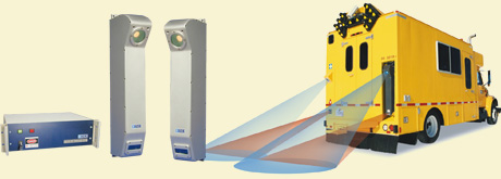
雷射道路影像檢測系統
Laser Road Image System, LRIS |
 |
|
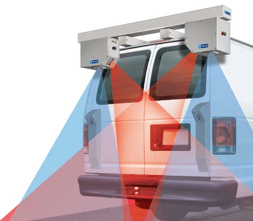
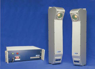
PAVEMETRICS’s laser road imaging
system (LRIS) is composed of
two high resolution linescan
cameras andlasers that are
configured to image 4m
transverse road sections with 1
mm resolution at speeds that can
reach 100 km/h. This patented
imaging system was,designed to
increase the contrast and
visibility of both small
longitudinal and lateral road
cracks.
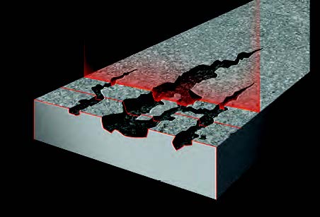
The LRIS optical configuration
increases the visibility of even
the smallest cracks by using the
incident illumination angle of
the laser to cause the cracks to
project shadows.
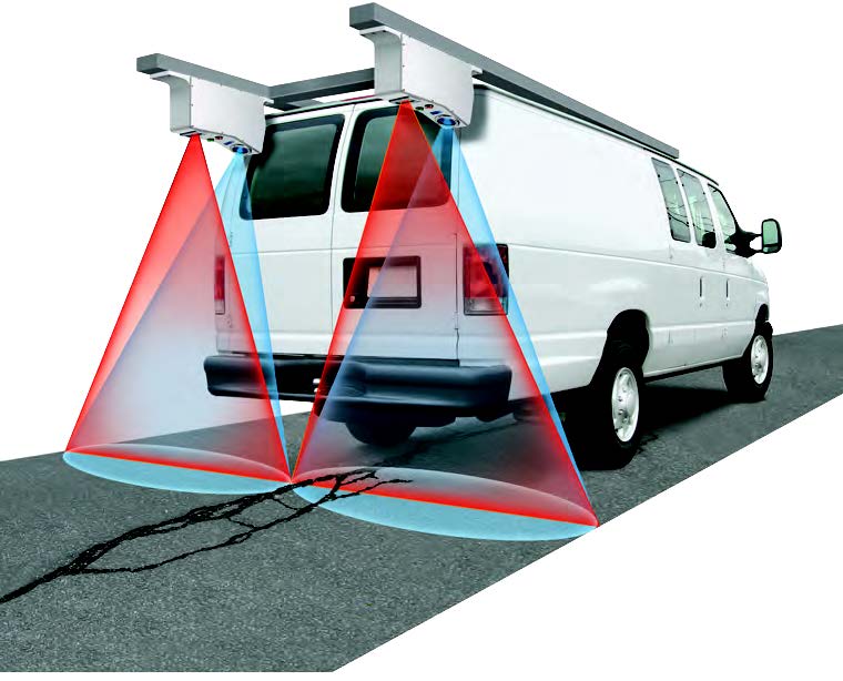
Using high power laser line
projectors and advanced optics,
the LRIS system is very robust
to variations in outside
lighting conditions and shadows
cast by roadside objects,
viaducts and the inspection
vehicle itself. |
 |
KEY FEATURES
specificat ions
-
Image size: 4096 pixels/line
-
Line rate: 28000 lines/s
-
Image width: 4 m (3950 mm
nominal)
-
Laser class: 3B
-
Power: 250W at 120/240 VAC
-
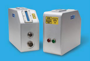
Sensor size (approx.): 300
mm(H) x 375 mm(L) x 200 mm(D)
-
Sensor weight (approx.): 20
kg
|
 |
|
 |
|
|
|
|
 |
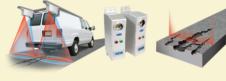
雷射道路路轍量測系統
Laser Rut
Measurement System, LRMS |
 |
|
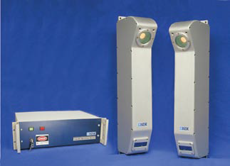
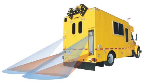
Pavemetrics’s laser rut
measurement system (LRMS)
is a transverse profiling device
that detects and characterizes
pavement rutting. The LRMS can
acquire full 4-meter width
profiles of a highway lane at
normal traffic speeds, with 2
options of maximum sampling
rate: 30 or 150 Hz. The system
uses two 3D laser profilers that
digitize transverse sections of
the pavement with 1280 points.
Custom optics and high-power
pulsed laser line projectors
allow the system to operate in
full daylight or in night-time
conditions. Road transverse
profile data can be collected
and processed in real time on
board the vehicle. Rut
extraction algorithms have been
developed to automatically
measure rut depth and width.
The system is delivered with a
complete DLL library of C/C++
functions allowing the user to
easily configure the sensors,
acquire transverse profiles,
extract road rut data, classify
rut type (short, multiple, long
radius) and validate the laser
profiler calibration. Over the
past years, this system has been
used on a continuous basis by
dozens of governments and
private agencies. Hundreds of
thousands of road kilometers
have been surveyed using this
technology. |
|
 |
|
KEY FEATURES
-
1280 point 3D transverse
profiles
-
Daylight or nighttime
operation
-
Short integration times for
minimal image blur at
maximum inspection speeds
-
A library of C/C++ functions
for easy use and integration
-
Proven performance
-
Inspection speeds up to 100
km/h
-
Rut depth and type (short,
multiple and long radius) is
evaluated.
BENEFITS
-
Immediate and precise
detection and
characterization
-
of rutting conditions
-
Optimization of road
maintenance funds
-
Improvement of safety due to
better road
-
pavement maintenance
|
SYSTEM
SPECIFICATIONS
-
Number of laser profiles: 2
-
Number of 3D points per
profile (max): 1280 points
-
Sampling rate: 30 or 150
profiles/s
-
Vehicle speed: 0 to 100 km/h
-
Profile spacing: adjustable
-
Transversal field-of-view
(nominal): 4 m
-
Transversal resolution
±2
mm
-
Depth range of operation:
500 mm (30 Hz)or 450 mm (150
Hz)
-
Depth
accuracy (nominal) ±1
mm
-
Laser profiler dimensions
(approx.):
108 mm(W) x 692 mm(H) x 220
mm(D)
-
Laser profiler weight
(approx.): 12 kg
-
Power consumption (max): 150
W at 120/240 VAC
|
|
|
|
|
|
|
|
|
 |
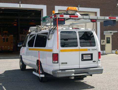
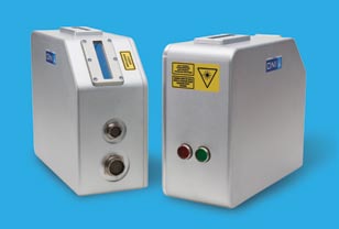
雷射道路裂縫量測系統
Laser
Crack Measurement System, LCMS
|
 |
|
The laser
crack measurement system (LCMS)
uses laser line projectors, high
speed cameras and advanced
optics to acquire high
resolution 3D profiles of the
road. This unique 3D vision
technology allows for automatic
pavement condition assessment of
asphalt, porous asphalt,
chipseal and concrete surfaces.
The LCMS acquires both 3D and 2D
image data of the road surface
with 1 mm resolution over a 4 m
lane width at survey speeds up
to 100 km/h.
LCMS data is acquired and
compressed in real time in the
survey vehicle so as to minimize
storage needs (<1Gb per km). The
collected data can then be
analyzed using Pavemetric’s
data processing toolbox (DLL
library of C/C++ functions).
This library has functions to
detect and analyze cracks, lane
markings, potholes, ravelling,
and macro-texture. Rutting is
also measured and characterized
using more than 4 000 points and
rut depth and type (short,
multiple, long radius) is
evaluated.
Concrete road surfaces can be
scanned to evaluate joints,
tinning and faulting between the
concrete slabs.IMUs can be added
to the sensors in order to
measure longitudinal profiles,
IRI, slope and crossfall. |
.jpg) |
KEY FEATURES
-
Automatic crack detection
and severity
-
4 160 point rutting (rut
depth, rut type)
-
Macro-texture measurements
over 100 % of the lane
width.
-
3D and 2D data to
characterise: cracks, pot
holes, ravelling, sealed
cracks, joints in concrete,
tinning, etc.
-
Day and night operation
-
Low power consumption
-
High resolution (1mm)
downward images
-
IRI and longitudinal profile
-
Slope and crossfall
SYSTEM
SPECIFICATIONS
-
Number
of laser profiles : 2
-
Sampling rate : 5 600
profiles/s or 11 200
profiles/s
-
Vehicle speed : 0 to 100
km/h
-
Profile spacing : 1 to 5 mm
(adjustable)
-
Transversal field of view :
4 m
-
Transversal accuracy : 1 mm
-
Transversal resolution : 4
096 points/profile
-
Depth range of operation :
250 mm (adjustable)
-
Depth accuracy : 0.5 mm
-
Laser profiler dimensions :
428 mm (h) x 265 mm (l) x
139 mm (w)
-
Weight : 10 kg
-
Power consumption (max) :
150W at 120/240 VAC
|
|
|
|
|
|
|
|
|
 |
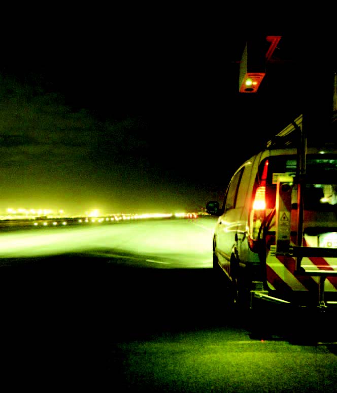
雷射跑道鋪面異物偵測系統
Laser
Foreign Object Debris Detection System,
LFOD |
 |
|
The laser
foreign object debris (LFOD)
detection system uses high speed
cameras, custom optics and laser
line projectors to acquire both
2D images and high resolution 3D
profiles of airport runways,
taxiways and aprons in order to
automatically detect even the
smallest objects at highway
speeds.
The LFOD system can be operated
both during daytime and
nighttime as well as under all
types of lighting conditions.
Sun and shadows as well as
various pavement types ranging
from dark asphalt to concrete
can be scanned at inspection
speeds from 0 to 100km/h.
Depending on the configuration
selected, an entire runway can
be scanned in only a few
minutes; automatically detecting
FOD as small as 2 mm in size.
FOD and GPS data is collected
simultaneously and is analysed
in real-time. Alarms can be
pre-set to trigger upon
detection of FOD of specific
sizes or volume. Included
software reports size, number
and location data for each of
the detected debris; thus
allowing operations and
maintenance personnel to quickly
decide whether to remove
individual threats or to proceed
with a general runway
maintenance program. |
 |
KEY FEATURES
-
Detection of FOD as small as
2mm
-
24 hour operation; day and
night-time
-
Automated detection; alarms
can be pre-set to trigger
upon the detection of
specific FOD sizes
-
Safe and efficient;
operational speeds from 0 to
100 km/h
-
Flexible configuration;
scanning width of 12 m-18 m
per pass.
-
Cost-effective installation;
typically can be mounted on
existing inspection
equipment
-
Accurate; GPS tagging of
detected debris
SYSTEM
SPECIFICATIONS
-
Number of laser profiles : 4
or 6 sensors
-
Sampling rate : 11,200
profiles/s
-
Transversal field of view :
12-16 m
-
Transversal resolution : 1.5
mm
-
Vertical accuracy : 1 mm
-
Laser profiler dimensions :
428 mm (h) x 265 mm (l) x
139 mm (w)
-
Weight : 10 kg
-
Power consumption (max):
300W at 120/240 VAC
|
|
|
|
|
|
|
|
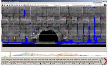 |
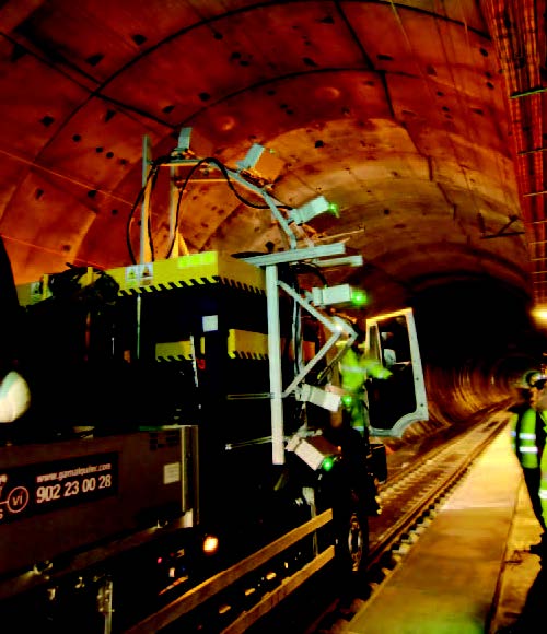
雷射隧道斷面掃瞄儀
Laser Tunnel
Scanning System, LTSS |
 |
|
The Laser
Tunnel Scanning System (LTSS)
uses multiple high speed laser
scanners to acquire both 2D
images and high resolution 3D
profiles of tunnel linings.
This system can scan a full
tunnel vault (24m) at 1mm
resolution image and 3D data at
acquisition speeds up to 20km/h.
Once digitized the tunnel data
can be viewed and analyzed
offline by operators using
multi-resolution 3D viewing and
analysis software that allow the
high precision measurement of
virtually any tunnel feature.
Automatic analysis software is
available to detect and rate the
condition of joints, faulting,
cracks, degraded concrete, wet
as well as wet and humid area
tunnel linings.
The LTSS technology was used to
scan high speed TGV rail tunnels
such as the 28km long Spanish
Guadarrama tunnel in full one
millimetre resolution (x,y,z) in
just 3 hours. The system was
also used to acquire data on the
Tokyo Metro System in Japan.
Vaults are scanned one half
going forward and the second
half coming back.
The LTSS is one hundred times
faster and 10 times more
accurate than typical LIDAR
technology. The LTSS can acquire
120,000,000 3D and 2D image
points per second at an accuracy
of 0.5 mm compared to typical
LIDAR accuracies of 5.0 mm for
just a few 100,000 points. The
standard LTSS configuration (6
sensors) allows for the scanning
of a full 12 m of tunnel surface
perimeter in a single pass.
Larger surfaces can be captured
through multiple passes (and the
images and data
“stitched”)
or scanning width can be
increased through the addition
of sensors. |
 |
KEY FEATURES
-
Full vault scanning.
-
1mm resolution images and 3D
data.
-
100 times faster and 10
times more accurate than
lidar scanning.
-
Measure tunnel features with
sub millimeter accuracy.
-
Visualize 1mm surface
defects from any point of
view without leaving the
office.
-
Scanning speeds up to
20km/h.
-
Automatic analysis software
of voussoir type tunnels
available.
-
Rail scanning options also
available.
SYSTEM
SPECIFICATIONS
-
Number of laser profiles : 6
sensors (standard)
-
Sampling rate : 5,000
profiles/s
-
Points per profile : 12,000
points (2D and 3D)
-
Total sampling rate :
120,000,000 points/s (2D and
3D)
-
Transversal field of view :
12m
-
Transversal resolution : 1mm
-
Vertical accuracy : 0.5mm
-
Laser profiler dimensions :
428mm (h) x 265mm (l) x
139mm (w)
-
Weight : 10 kg
|
|
|
|
|
| |
|
|